Moving Fluoroscopy
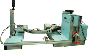
To overcome the limitations of marker-based kinematic measurements, which are affected by soft tissue artefacts (Taylor et al., 2005; Taylor et al., 2010), tracking fluoroscopic techniques for dynamically imaging internal skeletal structures and metallic implant components have been developed (Foresti, 2009; Zihlmann et al., 2006a; Zihlmann et al., 2006b). The video-fluoroscope c-arm unit was mounted on an automated trolley (maximum acceleration horizontal 9ms-2, maximum velocity horizontal 5ms-1) that allows dynamic tracking of the joint in question. The additional ability of the C-arm to track the joint at up to 1.33ms-1 vertically (maximum vertical acceleration 4ms-2), thus enabling the joint to be tracked throughout several gait cycles of free level and downhill walking as well as stair descent (List et al., 2017b).
The video fluoroscopic image capture was performed using a modified BV Pulsera videofluoroscopy system (Philips Medical Systems, Switzerland) with a field of view of 30.5cm, pulsed image acquisition rate of 25Hz, 8ms radiation time, 1ms shutter time of the CCD-sensor and an image resolution of 1000 x 1000 pixels with a grayscale resolution of 12 bits (Foresti, 2009; List et al., 2012a; List et al., 2012b; Zihlmann et al., 2006a; Zihlmann et al., 2006b).

Image distortion of the videofluoroscopic images was eliminated by a local correction algorithm (Foresti, 2009: List et al., 2012a; List et al., 2012b) using a reference grid containing approximately 1300 beads. Since the position of the beads relative to one another was known, the projection of the reference grid was restored by means of a polynomial approximation. The projection parameters of the videofluoroscopic system (focal distance and location of the principle point in the image plane) were determined using a least-squares optimization, which was based on five images of a calibration tube (300mm long with two Plexiglas® plates). At well defined positions (accuracy: ±0.03mm), each plate was filled with either 12 or 13 metal pellets, providing a total of 25 correspondence points.
Once the projection parameters of the fluoroscope were determined, its orientation and location relative to the video-photogrammetric system were determined (Foresti, 2009; List et al., 2017b). Here, the grid used for the image distortion correction was also equipped with six reflective markers screwed at predefined positions. The grid was rotated and displaced into multiple poses, with radiographs of the grid’s beads and simultaneous assessment of the marker positions allowing the relationship between their local coordinate systems to be determined. In order to determine the projection matrix, a least squares optimization was used to find the orientation and position of the fluoroscopy system relative to the origin of the video-photogrammetric set-up. Optical markers were additionally fixed to the C-arm of the moving fluoroscope to allow the position of the moving fluoroscope to be continually determined and referenced to the global lab coordinate system.
2D/3D registration of the 2D fluoroscopic images was performed by fitting CAD models of the implant components. The registration algorithm was based on the approach developed by Burckhardt et al., 2005, in which the pose of the 3D implant CAD models was determined through fitting a synthetic image of the CAD model to the fluoroscopic image by minimizing the difference in gradient magnitudes as well as pixel gray values within the region of interest defined by a slightly enlarged outline contour, to create the optimal matching scenario for each time point. Registration errors, assessed for a similar TKA, were <1 degree for all rotations, <1mm for in-plane and <3mm for out-of-plane translations (Foresti, 2009). The output is the 3D pose of the tibial and femoral components relative to the lab or image intensifier coordinate systems according to Grood and Suntay (1983).

